If you work in commercial or industrial electrical installations, you’ve probably heard a low-voltage (LV) distribution board called a “power hub” — and for good reason. That’s where electricity from the main supply gets split, measured, and routed to circuits that power everything from office outlets to factory equipment. But no matter how well we build these boards, they’re only as safe as their grounding system. For over a decade, I’ve run a small operation that designs and manufactures LV distribution boards, and I can’t tell you how often customers come to us thinking grounding is just a “set-it-and-forget-it” step on an order. It’s not. It’s the part that prevents shock hazards, stops fires from faulty wiring, and keeps the entire system compliant with codes. Today, I’ll break down exactly what grounding requirements look like for LV distribution boards, straight from the shop floor and the field calls we’ve gotten over the years. Lv Distribution Board
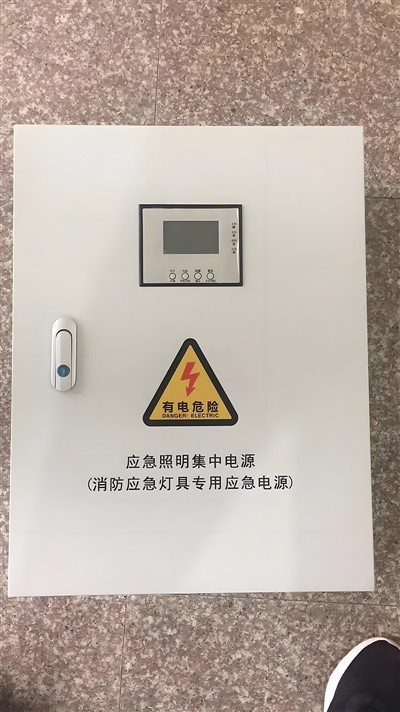
First, let’s clear up a common mix-up: grounding vs. bonding. A lot of people use these terms interchangeably, but they do different jobs. Grounding is connecting a conductive part of the system — like a neutral wire or the distribution board itself — directly to the earth. That creates a safe path for fault current to flow if something goes wrong, so circuit breakers can trip and shut power off fast. Bonding, on the other hand, is connecting all exposed conductive parts of the installation to each other, not to the earth. That includes metal pipework, conduit, and even the outer casing of your distribution board. We see this confusion all the time: a customer will order a board and skip the correct bond conductor size, then wonder why their system fails a pre-emptive safety check. It’s critical to get both right, and both tie back to LV-specific rules.
When we design our distribution boards, we base every grounding detail on local electrical codes — but most of our North American and EU customers follow two key sets of standards: the National Electrical Code (NEC) in the U.S., and IEC 60439, the international standard for low-voltage switchgear and controlgear assemblies. One of the first non-negotiable requirements is the main earthing terminal (MET) in the distribution board. This isn’t just a screw we add on the assembly line. The MET has to be sized to handle the maximum fault current that the distribution board’s main incoming supply can deliver. For example, if your service entrance is 200 amps, the MET can’t be a tiny 6mm screw. We spec 10mm minimum for 200-amp boards, and go up to 16mm for 400-amp and above, because that’s what NEC mandates to handle fault current without overheating or coming loose over time. Another rule the NEC enforces: the MET has to be clearly labelled, and it has to be physically separate from the main neutral terminal unless the system is a TN-C type. Wait, let’s explain that system type, because it’s another big piece.
LV distribution systems are split into three main earthing configurations: TN, TT, and IT. For most commercial and light industrial jobs, TN systems are the go-to, and they have two sub-types: TN-S, where neutral and earth wires are separate all the way, and TN-C-S, where they’re combined partway. Here’s the grounding requirement for TN systems: the distribution board’s earth terminal has to connect to the main earthing conductor (MEC) that runs back to the utility’s transformer neutral. If you’re in a TT system, which is common in rural areas where the utility doesn’t provide a dedicated earth conductor, you can’t just use the building’s metal pipes — you have to install a dedicated earth rod near the distribution board. That’s where we see mistakes: a customer will reuse a gas pipe as an earth electrode, and that’s a fire hazard, because pipes can be disconnected or corroded. For TT systems, NEC requires a separate, tested earth electrode with a resistance of 25 ohms or less, and we build distribution boards with a dedicated earth bar for that connection, not a random screw on the side of the casing.
Then there’s the grounding of the distribution board’s own metal parts. Every exposed metal part of the board — the enclosure, internal mounting rails, cable glands, and any removable panels — has to be bonded to the main earth bar. Why? If a live wire comes loose inside the board and touches the metal casing, that casing becomes energized. If someone touches it, they’d get a shock, unless the casing is bonded to earth, which trips the breaker instantly. We test every one of our boards for “continuity of protective conductors” before it leaves the shop: we run a low-voltage current through the earth path and check that the resistance is less than 0.05 ohms. That’s not just a box-ticking step; we learned early on that a loose gland or a thin mounting rail can create a high-resistance path, which is useless during a fault. I remember a customer who skipped that step on a 100-amp board for a restaurant — when a wire came loose, the casing was only connected through a 15mm screw with oxidized threads, and a cook got a minor shock. We fixed that board on-site by adding a bonding jumper across the rail and adding a second earth terminal, but it was a avoidable mistake.
Size of the protective earth (PE) conductor is another requirement that trips people up. The PE wire in a distribution board isn’t just a smaller version of the phase wire. IEC 60439 and NEC both have strict sizing rules: if your phase conductor is 16mm² or smaller, the PE conductor has to be the same size as the phase. If the phase is larger than 16mm², you can downsize the PE, but not below half the phase size. For example, a 25mm² phase wire needs a 16mm² PE wire, but not smaller. A lot of contractors try to save money by using a 6mm² PE wire for a 32mm² phase, and that’s a problem because the PE has to carry the full fault current. If it’s too small, it’ll melt before the breaker trips, and that causes an arc fault, which is a leading cause of electrical fires. We mark the PE size clearly on every board we build, and we include a note in our product datasheets explaining why that sizing matters — it’s saved a lot of customers from costly rework.
There’s also the rule about no “breakable” earth connections. In the past, some contractors would run a single earth wire from the utility, split it off in the distribution board, and use wire nuts instead of terminal blocks. That’s not allowed in most codes now, because wire nuts can come loose over time, especially with thermal expansion from current. All earth connections in an LV distribution board have to be secured with torque-rated screws, and for multi-wire connections, we use insulated terminal blocks or busbars, not just stacked screws. We test the torque on every terminal block before shipping, so customers don’t have to guess if a connection is tight enough. That’s a detail we learned after a 2019 call from a manufacturing plant: their distribution board’s earth wire had worked loose, a fault current caused an arc that burned through the enclosure, and they lost $50,000 in production. The mistake was a loose connection — we’ve since added torque tests as a standard step.
Bonding of extraneous conductive parts is another often-overlooked requirement. Those are metal parts in the building that aren’t part of the electrical system, like structural steel, water pipes, heating ducts, and conduit. The distribution board has to have a bonding terminal to connect these parts to the PE bar. NEC calls this the “equipment bonding conductor” (EBC) rule, and IEC has a similar requirement for main equipotential bonding. Why? If a fault happens in a piece of equipment, the extraneous parts can become energized, and if they’re not bonded, the fault current takes a longer path to earth, which means the breaker trips slower. We’ve had customers tell us they “don’t need that” because their system is new — but even a new building has steel pipes, and skipping that bonding step failed their first inspection. We now include a pre-installed bonding terminal on every distribution board, with a note about connecting it to the building’s structural grounding system.
Grounding also has to work for future expansion. A lot of people will order a 12-way distribution board now, thinking they’ll add circuits later, but they don’t leave extra space on the earth bar. That means when they expand, they have to add a new earth conductor, which requires cutting into the board or rerunning a larger cable. We design all our boards with 30% extra space on the main earth bar, so customers don’t have to modify the entire board later. For example, a 12-way board has space for 16 earth conductors, even if they only need 12. That’s a small add-on cost that saves customers from hiring an electrician to rework the board a year later.
Wait, let’s talk about testing, because grounding requirements don’t end when the board is installed. The NEC and IEC both require that after installation, you test the earth continuity, fault loop impedance, and earth electrode resistance. We include a free testing guide with every board we sell, and we even offer on-site testing for local customers. The earth continuity test checks that the PE path has low enough resistance for fault current to trip the breaker. The fault loop impedance test measures how much resistance is in the path from the phase wire, through the fault, to earth — if that impedance is too high, the breaker won’t trip fast enough, and that’s a shock hazard. I’ve seen boards that passed the factory test, but when installed, the long cable runs added too much impedance, so the customer had to upgrade the PE wire. That’s why we emphasize that testing is not optional; it’s part of meeting the grounding requirements.
Now, let’s address some common misconceptions we hear from customers. One is: “I have a grounded neutral, so I don’t need a separate earth.” That’s only true for TN-C systems, where neutral and earth are combined, but even then, the distribution board still needs a dedicated terminal for that combined conductor, and it has to be sized correctly. Another is: “Plastic enclosures don’t need grounding.” No — even if the board is plastic, internal parts like busbars and mounting rails need to be grounded, because if a live wire touches a metal rail, that rail becomes energized, and someone could touch it. We build plastic-enclosure boards with internal metal grounding rails, not just plastic parts, to cover that.
Over the years, we’ve adjusted our board designs to meet changing grounding requirements. For example, the 2020 NEC updated the rule for fault current rating of the main earthing terminal, requiring it to handle the maximum prospective fault current (PFC) of the service entrance for at least one second. Before that, many boards had terminals rated for 50 kA, but now we spec 100 kA for most 400-amp and above boards, because service entrances are getting more powerful. We don’t cut corners on that — a terminal that can’t handle the PFC will arc and fail during a fault, which is a catastrophic safety risk.
At the end of the day, grounding requirements for LV distribution boards aren’t just technical rules — they’re built to protect people and property. Every connection, every size, every terminal is there to make sure that if something goes wrong, power is shut off fast, and no one gets hurt. If you’re ordering an LV distribution board, don’t treat grounding as an afterthought. Make sure the board is built to meet the code for your system type, has properly sized PE conductors, continuity-tested earth paths, and extra space for future expansion.
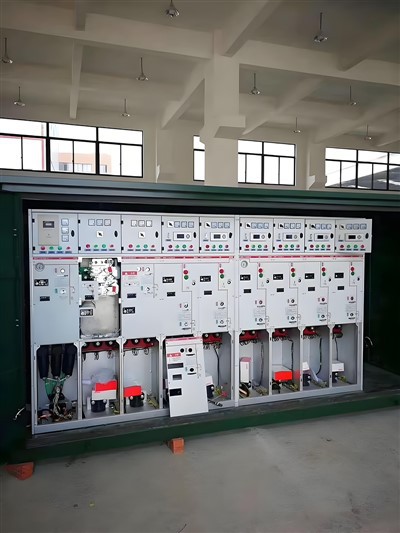
If you’re a contractor, building owner, or electrician working on a project and need an LV distribution board that meets all these grounding requirements, we’re here to help. We build custom and standard boards tailored to your specific load, system type, and code requirements, so you don’t have to guess about grounding details. Reach out to us to discuss your project and get a quote that fits your needs.
Distribution Chamber References
- National Electrical Code (NEC), 2023 Edition, National Fire Protection Association (NFPA), Quincy, MA.
- IEC 60439-1: Low-voltage switchgear and controlgear assemblies – Part 1: General rules, International Electrotechnical Commission (IEC), Geneva, Switzerland.
- Institute of Electrical and Electronics Engineers (IEEE) 142: IEEE Recommended Practice for Grounding of Industrial and Commercial Power Systems, Institute of Electrical and Electronics Engineers, New York, NY.
Anhui Nanxian Electric Co., Ltd.
With abundant experience, we are one of the most professional lv distribution board manufacturers and suppliers in China. We warmly welcome you to buy advanced lv distribution board for sale here and get quotation from our factory. All customized products are with high quality and low price.
Address: Factory Unit 03-2, Building 21, Feidong Yinfeng Industrial Park Co., Ltd., Northeast Corner of Manquan Road and Changle Road, Hefei Circular Economy Demonstration Park, Feidong County, Hefei City, Anhui Province.
E-mail: 541580567@qq.com
WebSite: https://www.nxelepower.com/
